CASSIOPEE
The CASSIOPEE beamline is dedicated to photoemission experiments in the 8 eV - 1500 eV photon energy range. The beamline uses two undulators, and the main optical elements are the entrance optics and the monochromator. After the monochromator, the beamline is divided into two branches, providing photons to two endstations (Spin-resolved Photoemission, and High Resolution Angle-resolved Photoemission), both connected to a Molecular Beam Epitaxy chamber.
The CASSIOPEE beamline is dedicated to photoemission experiments in the 8 eV - 1500 eV photon energy range. The beamline uses two undulators, and the main optical elements are the entrance optics and the monochromator. After the monochromator, the beamline is divided into two branches, supplying photons to two endstations (Spin-resolved Photoemission, and High Resolution Angle-resolved Photoemission), both connected to a Molecular Beam Epitaxy chamber.
Beamline news
All news
SOLEIL Highlights 2025

European School HERCULES 2026 at SOLEIL
Team

Technical data
- Energy range
-
8 – 1500 eV
- Energy resolution
-
E/ΔE from 20000 to 70000 as a function of photon energy
- Source
-
- Electromagnetic undulator HU256 (8 - 155 eV)
- Apple II undulator HU60 (100 - 1500 eV)
- Flux on first mirror
-
1.1015 Phot/s/0.1% bw
- Optics
-
3-mirrors set entrance optics
Plane-grating Monochromator (3 Variable Line Spacing-Variable Groove Depth gratings, working in the modified Petersen mode)
Two endstations are present on the beamline:
- Spin-resolved Photoemission endstation: Toroidal miror focussing (250x200 to 720x350 µm2 beam spot)
- High-resolution Angle-resolved Photoemission: Pseudo-Wolter focussing (40x20 to 100x100 µm2 beam spot)
- Flux on the sample
-
2.1013 Phot/s/0.1% bw
- Polarisation
-
Variable Polarisation (Circular, Linear horizontal and vertical)
- Beam spot size on the sample
-
- Spin-resolved Photoemission endstation: 250x200 to 720x350 μm2
- High-resolution Angle-resolved Photoemission endstation: 40x20 to 100x100 μm2
- Sample Environment
-
3 ultra-high vacuum chambers:
- Molecular Beam Epitaxy chamber with surface science equipments (LEED, AES, RHEED, sputtering)
- Spin-resolved Photoemission endstation: Temperature from 40 to 300 K - 4 axis manipulator (3 translations, one polar angle rotation)
- High-resolution Angle-resolved Photoemission endstation: Temperature from 20 to 300 K - 6 axis manipulator (3 translations, 3 rotations)
- Detectors
-
- Spin-resolved Photoemission endstation: MBS-A1 Analyser equipped with spin rotator and FERRUM V-LEED spin-detector.
- High-resolution Angle-resolved Photoemission endstation: Scienta R4000 with wide-angle lenses
Scientific opportunities
| Low dimension systems | Graphene, topological insulators... |
|---|---|
| Complex Oxides | Cobaltates, Pnictides, Cuprates, Vanadates, multiferroïcs... |
| Surfaces and Interfaces | Semiconductors Interfaces (Sn/Ge, Sn/Si, Alkali/Si:B), molecules/surfaces, biological species/surfaces... |
| Spintronics | Magnetic tunnel junctions, Heusler compounds, Functional oxides interfaces... |
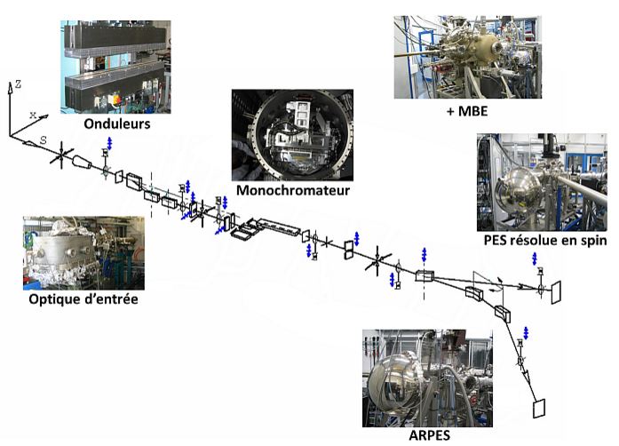
The CASSIOPEE beamline uses two undulators. The different optical elements are:
- The entrance optics
- The monochromator and its plane gratings
The beam can be directed at two different endstations:
- Spin-resolved PhotoEmission Spectroscopy (Spin-resolved PES)
- High-resolution Angle-resolved PhotoEmission Spectroscopy (HR-ARPES)
Both are connected to a Molecular Beam Epitaxy chamber (MBE)
Undulators
Two undulators are necessary to cover the large photon energy range available at Cassiopée. They were designed and characterized by the SOLEIL Insertion device Group (Antoine Daël, Oleg Chubar, Fabrice Marteau, Chamseddine Benabderrahmane, Marie-Emmanuelle Couprie and Fabien Briquez).
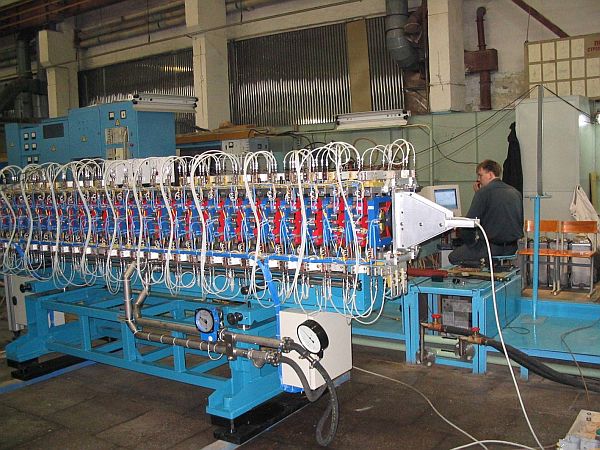
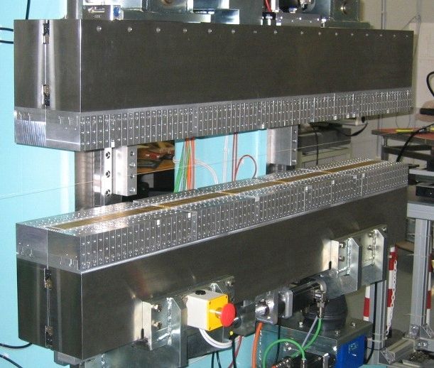
For low photon energies, Cassiopée uses a HU256 electromagnetic undulator, with a 256 mm period, which was designed at SOLEIL and built at the Budker Institute of Nuclear Physics in Novosibirsk (Russia). This undulator provides linearly (vertical or horizontal) or circularly (left or right) polarized photon in the 8 eV-155 eV range (see Figure 1).
For the high photon energies, Cassiopée uses a HU60 permanent magnet Apple II type undulator, with a 60 mm period, which was designed and built at SOLEIL. This undulator provides linearly (vertical or horizontal) or circularly (left or right) polarized photon in the 100 eV-1500 eV range (see Figure 2).
Entrance Optics
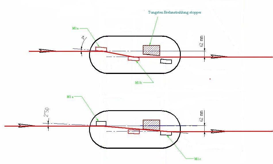
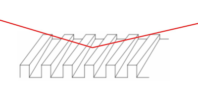
The first optical elements play a key role in the beamline's stability and performance. Cassiopée entrance optics is made of three silicon mirrors (M1a is a plane mirror and M1b and M1c are two spherical mirrors) attached to the same rotating table whose rotation axis is vertical, in the plane of M1a surface. Ideally, the surfaces of the three mirrors should be parallel (see Figure 3).
These three mirrors (and especially M1a) have to absorb the power radiated by the ring and the insertion devices, without suffering any deformation. In the worst condition, this absorbed power can be as high as 250W. Therefore, these three mirrors are cooled down at a temperature of 100 K, where the silicon dilatation coefficient is zero, to avoid any thermal bump at the impact point of the photon beam. This is done by a 9 bars liquid nitrogen closed loop circulation.
The entrance optics has two working positions:
- A low energy position, in the 8 eV-155 eV photon energy range, when HU256 is used. In this case, the rotating table is set for an incident angle of 5.02° on M1a. The photon beam is then reflected towards M1b, whose radius is calculated to focus the HU256 source point onto the monochromator’s gratings.
- A high energy position, in the 100 eV-1500 eV photon energy range, when HU60 is used. The rotating table is then set for an incident angle of 2.44° on M1a. The photon beam is then reflected towards M1c, whose radius is calculated to focus the HU60 source point onto the monochromator’s gratings.
When going from one position to the other, an in-vacuum motor can also be used to rotate only M1a, in order to adjust the parallelism between M1a and the other concerned mirror. These two reflections shifted the useful VUV radiation axis from 62 mm in the horizontal plane. Hence, a tungsten rod can be placed along the undulators axis to block the gamma rays emitted by the ring (which go through the silicon mirror).
Monochromator
Monochromator Geometry
The design of the CASSIOPEE plane grating monochromator was done by the SOLEIL Optics Group. The starting point is the well-known SX700 monochromator, but several modifications have been made.
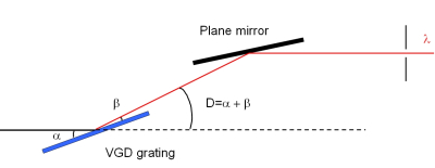
The working principle of the monochromator is shown in Figure 2. One can choose the incident angle α of the white beam on the plane grating by rotating the grating around an horizontal axis. The β angle can be chosen by rotating the plane mirror, above the grating, around a horizontal axis located below the grating plane, to ensure a constant height of the outgoing beam. For a given couple (α, β), the selected wavelength λ is given by the gratings law:
cos α - cos β = N.k.λ
where k is the diffraction order (-1 for CASSIOPEE) and N is the number of lines/mm on the grating. The CASSIOPEE monochromator contains three different gratings with 400 l/mm, 800 l/mm and 1600 l/mm.
The CASSIOPEE monochromator is designed to work in the “modified Petersen mode”, which means that α and β are always chosen to fulfil the following equation:
sin β ⁄ sin α = constant ≈ 0.2
to ensure an optimal resolution on the whole photon energy range.
Monochromator Gratings
The gratings of the CASSIOPEE beamline focus the photon beam by using varied line spacing (VLS). The groove depth also varies along the direction perpendicular to the beam. Hence, by choosing the position of the grating with respect to the beam, one can choose the groove depth seen by the beam to enhance the grating reflectivity at each photon energy. They were made by the Jobin-Yvon company (Longjumeau, France).
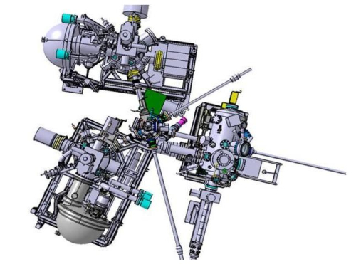
Overview of the three Cassiopée experiments
The three Cassiopée experiments are:
- Spin-resolved Photoemission experiment
- High Resolution Angle-resolved Photoemission experiment
- Molecular Beam Epitaxy chamber
These chambers are connected to a Crossway chamber, and samples can be transferred in UHV from one chamber to the other as shown on Figure 1.
The samples are mounted on Omicron-type plates. See this section Users information for practical details.
Spin-resolved PhotoEmission Spectroscopy
Detectors
The Spin-Resolved Photoemission experiment features a MBS-A1 Analyzer and a FERRUM V-LEED spin detector system. Photoelectrons are collected by the MBS-A1 within ±15° angular acceptance, the analyser is mounted with horizontal entry slit. The exit plane hosts a MCP+camera system for regular ARPES measurements and electrostatic lenses deflectors allow to access specific emission angles within the detector acceptance avoiding sample rotation. A secondary aperture is fitted in the analyser exit plane where a transfer optic system guides the photoelectrons to the spin-resolved scattering chamber. Along this path, the photoelectrons pass through the spin rotator which aligns the selected spin component to the spin detector quantization axis. The photoelectrons then imping on the FERRUM scattering target, which filters them accordingly to their spin orientation, and are finally collected by a channeltron. In addition, the in-plane magnetization of the target (i.e. direction and sign) can be controlled via two pairs of coils, thus offering means to rule-out instrumental asymmetries in the data.
Spin Target Preparation
The target consists in an oxidized iron film deposited on W(100) substrate. Fresh oxidized iron targets can be routinely prepared in the FERRUM chamber which hosts an e-beam Fe evaporator, while the target sits in a sample holder equipped with an e-beam heater.
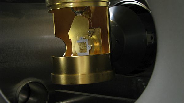
Sample Environment
The Spin-Resolved Photoemission experiment is equipped with a 4-axis manipulator, with a motorized Z translation, manual X and Y translations, and manual θ rotation (see Figure 2). The sample can be cooled down to 40 K with a liquid He open cryostat. It is possible to heat the sample up to 300 K while flowing cold gas through the transfer line.
The sample can be magnetized either in-plane or out-of-plane under 0.1 T outside the measurement chamber.
Beam Size
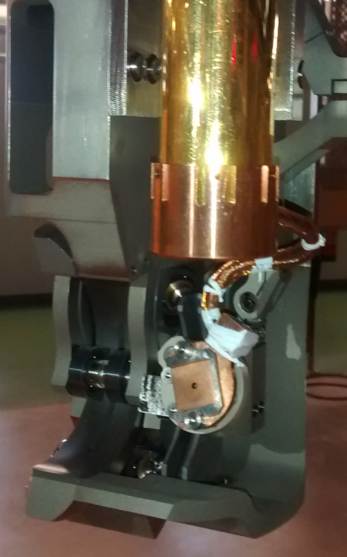
The beam is sent to the Spin-Resolved Photoemission experiment by a toroidal mirror which also focuses the beam. The beam size is quite large, not to damage the sample during long acquisitions (Figure 3).
High-resolution Angle-resolved PhotoEmission Spectroscopy (ARPES)
Detectors
The Cassiopée High Resolution Angle Resolved Photoemission experiment is equipped with a Scienta R4000 electron analyzer, whose angular acceptance is ±15° (Scienta Wide Angle Lens). This analyzer can be mounted with its slits either vertical or horizontal.
Sample Environment
The High Resolution Angle Resolved Photoemission experiment is equipped with a fully-motorized 6 axis sample holder with X, Y and Z translation and θ, χ and Φ rotation (see Figure 4). The experimental chamber is equipped with a ColdEdge Stinger closed cycle cooling system which provides a minimum temperature of ~20K on the sample’s stage. The Scienta analyzer is mounted with vertical slits. The 30° vertical angular acceptance and the θ rotation of the sample allow to scan a large part of the reciprocal space.
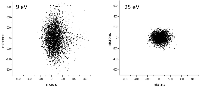
Beam Size
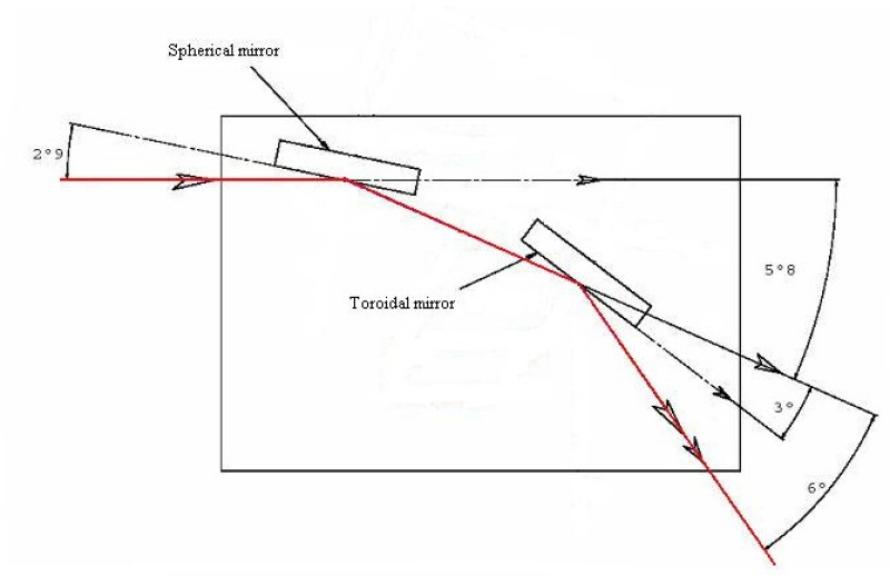
The beam is focussed by a pseudo-Wolter optics located just before the experimental chamber. It consists in a spherical mirror followed by a toroidal mirror (see Figure 5).
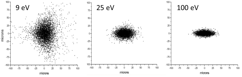
The size of the beam depends on the photon energy, but is always of tens of microns. Ray tracing calculations are show in Figure 6.
Molecular Beam Epitaxy Chamber (MBE)
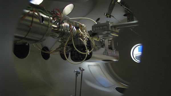
The Cassiopée MBE chamber is equipped for surface preparation and characterization, as well as for thin film deposition (see Figure 7):
- 3-keV ion gun (OCI IPS3-D)
- Cylindrical mirror analyzer for Auger spectroscopy (Staib ESA100)
- LEED (Omicron SpectaLEED)
- RHEED (SPECS RHD30)
- 10 crucibles 3kW e-gun evaporator (Thermionics)
- Transferable electron bombardment evaporator (Omicron EFM3)
- Quartz microbalances (Inficon IC/5 controller)

Sample Holder
The MBE sample holder has three positions for the sample (see Figure 8):
- Position 1: Electron bombardment heating (up to 1000°C) and azimuthal rotation for RHEED experiment.
- Position 3: Direct current heating (for semi-conductors).
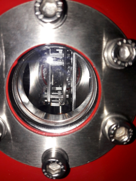
Ultra-High Vacuum Suitcase
The Cassiopee beamline has a reliable and easy way to transfer air-sensitive samples between the laboratories which grow such sample and the Cassiopée beamline located at Synchrotron SOLEIL. Such ultra-high vacuum (UHV) suitcase weight 15 kg is autonomous for several days thanks to a Ionic-pump combined with a NEG pumping device and compatible with Cassiopée beamline sample holders and sample environment. It's also easy to mount and handle.
The UHV suitcase can be mounted on CF40 flange both at Synchrotron SOLEIL beamline and on the other laboratories vacuum end-stations. After proper bake-out and NEG conditionning, we provide a base pressure of 10-10 mbar. We are able to measure indirectly the pressure by measuring the current of the ionic pump.
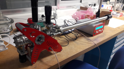
For sample storage, a sample park with 5 slots is provided.
For sample transfer, we have a linear/rotary feedthrough which can go up to 400 mm after the transfer flange, a port aligner and port views to allow easy transferring.
The total weight does not exceed 15 kg and the total length does not exceed 1100 mm. To be easily manipulated, protection plates and carrying handles are present.

Cassiopee beamlines uses “SHOM” plates for sample mounting: the UHV suitcase is compatible with such plates (see User Information/Sample Holders item on this page).
A more comprehensive manual can be downloaded at the bottom of this page.
Sample Holders
Samples are mounted on Omicron-type plates (see Figure 1a). They can be of different thicknesses to maintain the manipulator rotation axis in the plane of the sample surface (see Figure 1b), which is crucial for ARPES measurements. In any case, the total thickness (plate + sample) must be 5 mm.
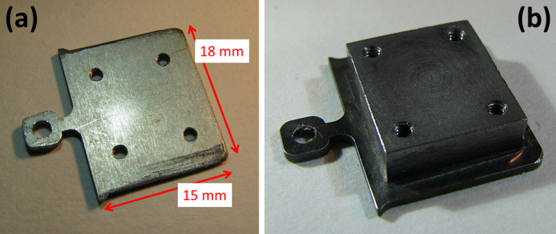
Figure 1: Flat Omicron-type plate with tapped holes (a) and thickened plate (b). The maximum size of the sample is 12x12 mm² since 2 mm should be left uncovered on every side.
We also have special plates for direct current heating (see Figure 2) that can also be used in the in-situ bias application area (under construction).
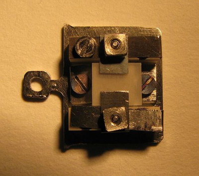
Figure 2: Omicron-type plate for direct current heating. The maximum size of the sample is 7x7 mm² in this case.
Sample Loading and Storage
Loading Samples
The samples can be quickly introduced in UHV thanks to a load-lock mounted on the crossway chamber (see Figure 3).
Storing Samples
Inside the crossway, samples are stored on a carousel which can contain up to 16 samples (see Figure 4).
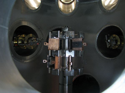
Figure 4: View of the carousel inside the crossway chamber.
Shipping Goods
Ligne CASSIOPEE
Synchrotron SOLEIL
Orme des Merisiers BP 48 - Saint Aubin
91192 - Gif-sur-Yvette, FRANCE