TEMPO
TEMPO is a soft X-ray beamline optimized for dynamic studies of electronic and magnetic properties of materials using photoelectron spectroscopy.

TEMPO is a soft x-rays beamline adapted to the dynamic studies of the electronic and magnetic properties of materials. The project gathers various spectroscopic studies around its specificity, i.e. taking into account the temporal variable. This regards more specifically:
- the determination of the kinetics of chemical reactions at interface and surface by rapid photo-emission in the millisecond range. The high flux coupled to the high energy resolution of the electron energy analyser and of the beamline will allow the user to study the evolution of the chemical environment (surface coordination, chemical bonding with different elements) of selected chemical atoms at the surface using spectroscopic signatures in the electronic states. Physisorption kinetics, chemisorption or dissociation of molecules on a substrate, interface formation and interdiffusion. The understanding of these processes is the key point to build new magnetic materials or to control chemical reactivity and catalytic properties.
- the dynamics of magnetisation reversal in nanostructures, using the temporal characteristics of Soleil at the scale of dozens of picoseconds , a problem of major significance for the magnetic storage of information at ultra-high density. These experiments will be performed using different techniques with different probing depths : X-ray magnetic circular dichroism, Magnetic dichroism in photoemission.
- carrying out pump-probe experiments with two photons (laser + synchrotron radiation) for the study of excited states using synchrotron impulses in the temporal range of a picosecond.
The TEMPO beamline results from the transfer of the SB7 beamline [1] of SuperACO onto an insertion device source of Soleil. It covers the photon energy range between 50 eV and 1500 eV. This energy range is particularly well suited for magnetic materials studies and for chemistry applications. On the one hand, UPS (valence band) photoemission is feasible at h n =50 eV. On the other hand, the whole range of K edges (C, O, N, F 1s) of organic molecules, the 4 th period transition metal L (2p) edges of transition metals (with applications to metal-organic molecules and metal surfaces), and M edges of rare earths is covered.
Beamline news
All TEMPO news
SOLEIL Highlights 2024

SOLEIL's contribution to the Energy Transition
Team

* External service provider, temporary or collaborator
Videos
All videos
The nanoworld at SOLEIL
The lights of SOLEIL
Technical data
- Energy range
-
50 – 1500 eV
- Energy Resolution
-
E/ΔE better than 104
- Source
-
HU80 and HU44 Apple II type Insertion Devices
- Flux @ first optical element
-
2.1015 Phot/s/0.1% bw à 100eV
- Optics
-
I.D. source toroidal imaging for femtosecond slicing separation Monochromator: VLS plane gratings, spherical mirrors
2 branches: two experimental stations operating alternatively
- Flux on sample
-
EAbout 4 1013 Phot/s/0.1%bw
- Polarization
-
Variable polarization (Circular, linear horizontal and vertical)
- Beam size at sample
-
10x40 μm2 (1st branch); 100x100 μm2 (2nd branch)
- Equipment 1st branch (UHV – Surface Science)
-
Sample Environment
Preparation
Preparation chamber, sample transfer system and fast entry lock Ar- sputtering, water cooled evaporators Sample holders for metals, conventional semiconductor samples and lamellar solids (graphite,MoS etc.)
Characterisation
LEED, Magneto optical Kerr effect Cooling (50 K) and heating (1200 K) sample environment
Detectors
SCIENTA 2002 electron energy analyser with 2D delay line detector for time resolved experiments
Secondary electrons spin polarization (high energy(100kV) Mott detector)
- Equipment 2nd branch
-
Ready to accept user dedicated experimental stations
Scientific opportunities
| Surface Science | Analysis and chemical imaging of thin films and protection layers Real time surface alloy formation: kinetic studies Semiconductor physics |
|---|---|
| Magnetism | Linear and circular magnetic dichroism in soft x-ray absorption and photoelectron spectroscopies. Magnetization dynamics at picosecond and sub-picosecond* time scale |
| Chemistry | Laser excited photo-chemistry at picosecond and sub-picosecond* time scale Surface chemical reaction kinetics Catalytic reactions . |
| Applied Research | Analysis and expertise of various applied problems in surface science and time dependent applications. |
TEMPO is a soft-x-ray beamline designed for time dependent studies of electronic and magnetic properties of materials using photoelectron spectroscopy experiments.
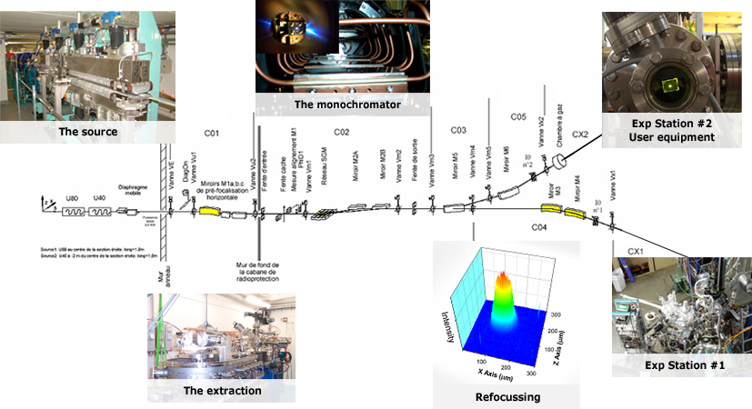
Source
The beamline is equipped with two APPLE II helical insertion devices. They have periods of 44 mm and 80 mm and allow us to cover the whole energy range of the beamline using the first harmonic.
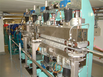
The picture shows the two insertion devices installed in the straight section of Soleil. The HU80 is quasi-periodic to reduce as much as possible the higher harmonic contamination of the photon beam.
We can see here the magnetic arrangement.
Insertion Device calibration and alignment
The energy calibration of the insertion devices emission is a critical point of the beamline operation in terms of flux, polarization end reliability of the installation.
Since the very beginning of the beamline commissioning this activity was done in collaboration with the insertion device group of Soleil (GI). Calibration tables for the gap and the phase values of the APPLE II insertion devices where calculated by GI as a function of the photon energy to fit our experimental data obtained by measuring the emission spectra of the ID. The calibration was done for four polarization configurations: linear vertical and horizontal, circular left and circular right. An essential step of the calibration procedure was to define properly the diaphragm size (ID emission cone) and his position at the center of the emission cone of the undulator. The diaphragm was closed to 400 μm and scanned in the horizontal and vertical plane. For each position we obtained the energy spectra presented in Fig. 1 as a function of the photon energy. While moving to the ID axis, the intensity increases and the photon flux maximum is centered to higher photon energies. In the inset, are presented the maximum intensity and the photon energy of the maximum extracted from the spectra as a function of the diaphragm position.
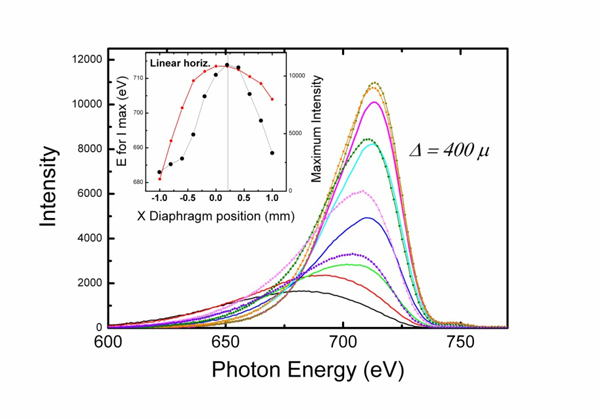
Fig. 1: Photon flux spectra measured as a function of the photon energy by scanning vertically the diaphragm closed at 400 microns. The measurements are performed on a calibrated photodiode placed at the sample position. The maximum intensity and the energy of the maximum are reported in the inset as a function of the diaphragm position to define the axis of the insertion device.
The procedure was applied for the HU44 and the HU80 for the four main polarizations and at some characteristic photon energies. Using the fast scan procedure the data in Fig. 1 can be measured in less than one hour.
SR Extraction
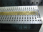
The first mirror chamber is placed in the radioprotection hutch at about 20 meters from the source. The photon beam is first deflected by a plane mirror. Depending on the incidence angle it can follow two optical paths characterized by a deflection angle of 2 and 4 degrees. The beam is then reflected by a thoroidal mirror placed at 2 or 4 degrees for high and low energy photon respectively.
The Silicon mirrors are Pt coated and cooled to 100K by a closed circuit of high pressure liquid nitrogen.
The picture shows the three mirrors support inthe clean room during the mirror alignment. The copper tubes are in closed circuit for liquid nitrogen cooling.
Alignement diagnostics
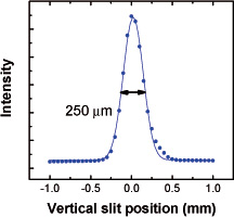
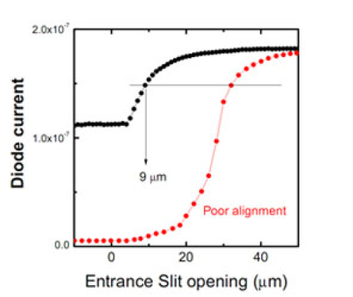
Two slits are placed at the horizontal and vertical focal points of the toroidals mirrors. The transmitted intensity is used as a diagnostics of the extraction region (M1 mirrors) alignment. On the left you can see the intensity beam profile obtained scanning horizontally the position of a vertical slit 50 microns wide, placed before the gratings. It allow us to determine the correct alignment in the horizontal plane. The transmitted intensity presented on the right is measured while scanning the opening of the entrance slit. The beam size depends on the photon energy, but when the alignment is good, more than 50% of the intensity is transmitted through the minimum slit width of 5 microns.
Monochromator
The monochromator is composed by three plane gratings and two spherical mirrors. The gratings presents a Variable Line Spacing (VLS) to focus on the exit slits and a Variable Groove Depth (VGD) to optimize total photon flux and harmonic rejection at each photon energy.
The monochromator is then characterized by two optical paths : one for low energy ranges and the other for high energy ranges. The photon energy intervals are summarized in the table.
| Low energy optical path (Mirror A) | High energy optical Path (Mirror B) |
|---|---|
|
|
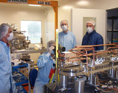
Alignment procedure
Picture taken during the first monochromator alignemnt. The alignment was carefully verified by Alignment group and Optic group.
Energy Resolution
The resolution tests were performed measuring the ion yield spectra in the energy region close to the resonant 2p excitation of atomic argon as well as the rydberg series of helium and the 1s excitation of molecular nitrogen. The spectra were obtained by monitoring the total number of ions produced in the interaction region between the monochromatic synchrotron radiation beam and an effusive gas jet emanating from a small nozzle. The results obtained for Helium, Argon and Nitrogen are shown in the following panels. In order to extract the Gaussian broadening introduced by the beamline, we have to take into account the intrinsic Lorentzian width of lines.
The resolving power E/ΔE is higher than 10.000 for the three energies.
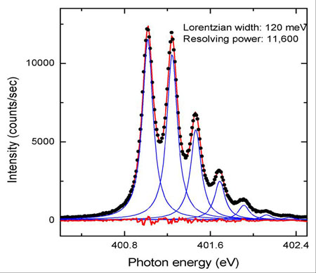
Nitrogen 1s absorption edge
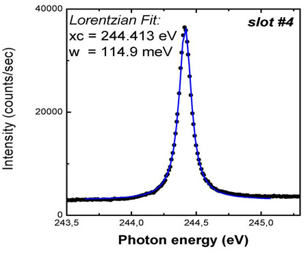
Ar absorption
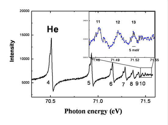
He
Refocussing
Spot size on the branch line
The spot size has been measured positioning a fluorescent YAG screen at the sample position and taking an image with CCD camera and a calibrated magnification optic placed at about 300 mm (S. Kubsky, Surface Laboratory).
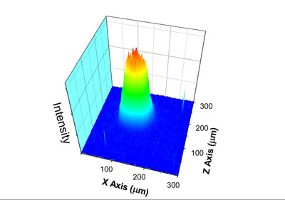
3D representation of the photon beam intensity
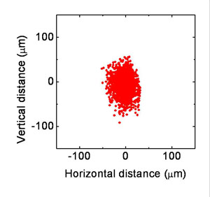
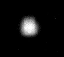
Comparison of the image obtained by ray tracing calculation(left) and of the measured focal spot (right) for the same field of view: 300μm x 300μm.
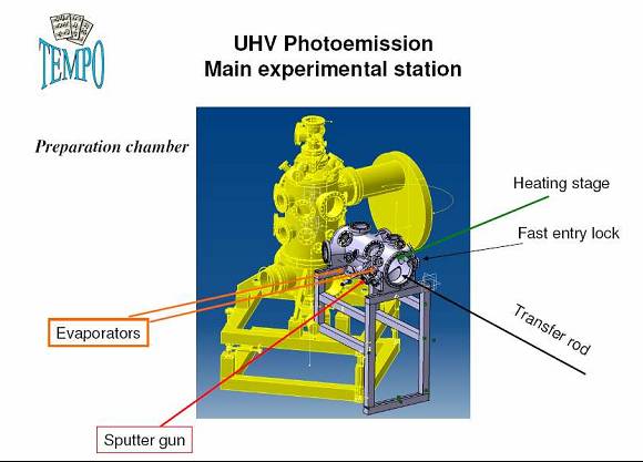
Station exp #1: UHV Photoémission
UHV Photoemission
The main branch of the TEMPO beamline is equipped with a UHV system for surface science experiments. It is composed by a main chamber equipped with a Scienta SES 2002 electron energy analyzer (equipped with a delay line detector) and a preparation chamber with a sample transfer system and a fast entry lock. Ar- sputtering, water cooled evaporators and LEED characterization are available. We have developed two sample environments: one for magnetic dichroism experiments where about 100 Oersted can be applied in the measuring position and one for direct heating of semiconductor samples by current flow.
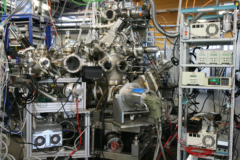
The UHV Photoemission experimental station in 2008
Detector For Time Resolved experiments
An important part of the TEMPO beamline scientific project is based on time resolved photoemission experiments performed using a pump probe technique. Possible applications are to studies of the electronic structure of laser excited states or the dynamics of surface magnetization.
The relaxation time of these phenomena can be longer then the interbunch period. It is then indispensable to associate each detected photoelectron to the synchrotron bunch which created it. If this identification is possible , then each repetition rate of the pump can be used for the experiments and the state excited by the laser pump can be probed by the Syncrotron Radiation pulse as a function of the delay Δt between the two pulses.
The time resolution of the experiment is then limited only by the S.R. pulse width: 30 ps at SOLEIL
We modified the Scienta SES 2002 electron energy analyser by replacing the CCD Camera by a delay line detector (G.Cautero and coworkers, Elettra, Trieste, It) which can associate each detected photoelectron to the Soleil Clock. This new configuration allows us to perform photoelectron spectroscopy experiments using the isolated bunch when Soleil is injected in hybrid mode.
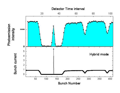
In the picture the photoemission intensity measured as a function of time on a revolution period (about 1.2 μs) is compared to the Soleil bunch structure during a run in hybrid mode.
Station exp #2
This focal spot has been used for the photon beam commissioning. Here we have performed gas phase experiments (M. Meyer, LIXAM) to measure the monochromator resolving power and the total photon flux with a calibrated diode.
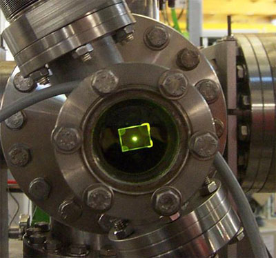
First photon beam image at the focal spot registered at the TEMPO beamline
The picture was taken on February 12th 2007 with the monochromator in total reflection mode. The well centered spot is the result of the good work done by the alignment group.
External user equipments can be installed at this focal point:
XPEEM from Lab. L. Néel (Grenoble)
The PEEM from Louis Néel Laboratory (Jan Vogel) has been installed on the branch line since 2008 to perform magnetization dynamics experiments.
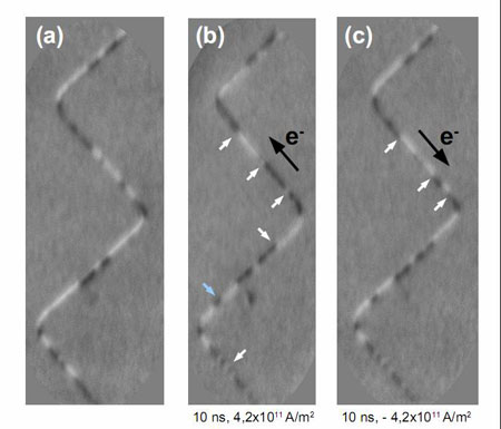
(a) Initial magnetic domain structure of a 200 nm wide nanowires after applying some magnetic field pulses.
(b) Domain structure after application of one 10 ns long current pulse with a current density of 4.2 x 10¹¹ A/m2. The direction of electron flow is indicated in the image. The small white arrows indicate domain walls that have moved, in the direction of the electron flow. The blue arrow points to a new domain that has nucleated.
(c) Domain structure after application of an identical pulse, but in the opposite direction. Some of the domain walls, indicated by small white arrows, have moved back in the opposite direction. These data confirm that the domain wall motion is due to the spin torque effect induced by the spin polarized current. However, the domain wall motion is not exactly reversible, indicating the strong role played by domain wall pinning in our system.
NanoEsca CEA @ TEMPO Beamline
The NanoESCA (Omicron Nanotechnology) experimental station of CEA-LETI, has been installed for two periods of several weeks in 2009 and 2010. The spectro-microscopy set-up is composed by two hemispherical analyzers in cascade which compensate the aberrations introduced by only one hemisphere. The transmission is high enough to work with a high energy resolution (Up to 100meV) in valence band and core level spectromicroscopy experiments. The photon flux was high enough to keep a good lateral resolution of 100nm in valence band experiments and below 100nm in core level.
A picture of the NanoEsca station installed on the branch of the TEMPO beamline is shown here. The system was operational on the X-ray beam after few days of installation, alignment and baking. The equipment was open to external user projects.
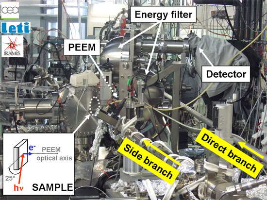
The NanoEsca experimental Station @ TEMPO
The TEMPO beamline is opened to external users since december 2007. On this page you will find a quick description of research projects and the external users list.
Collaborations
Laboratoire de Chimie Physique - Matière et Rayonnement
Université Paris VI
11, rue Pierre et Marie Curie
75 231 Paris Cedex 05
Francois Rochet
Jean Jacques Gallet
Fabrice Bournel
George Dufour
Construction and commissioning of the main experimental station (UHV photoemission) and of the preparation chamber.
web site: http://www.lcpmr.upmc.fr/theme2.html
IDMAG, Laboratoire de Physique des Solides
Orsay, France
Gregory Malinowski
André Thiaville
Alexandra Mougin
web site : http://www.lps.u-psud.fr/collectif/gr_25/default.htm
APE Beamline
Elettra Synchrotron Light Laboratory
S.S. 14 Km 163.5, in Area Science Park
34012 Trieste (Italy)
Damjan Krizmancic
Software development for the new delay line detector installed on the Electron energy analyser and Beamline data acquisition programs.
Web site: http://www.elettra.trieste.it/experiments/beamlines/ape/index.html
Instrumentation and Detectors Labs
Elettra Synchrotron Light Laboratory
S.S. 14 Km 163.5, in Area Science Park
34012 Trieste (Italy)
Giuseppe Cautero
Luigi Stebel
Paolo Pittana
Rudi Sergo
Enrico Braidotti
Construction, installation and commissioning of the new Delay line detector installed on the SES 2002 electron energy analyser.
Web site: http://www.elettra.trieste.it/organisation/experiments/laboratories/instrumentation/
Users list
Paris Region
Laboratoire de Chimie Physique - Matière et Rayonnement,
Université Pierre et Marie Curie Paris VI
1. F. Rochet, J.J.Gallet, F. Bournel, G. Dufour
2. Boris VODUNGBO, Renaud DELAUNAY , Jan LUNING
3. Philippe PARENT, Carine Laffon
4. Pascal LABLANQUIE Francis PENENT, Lidija ANDRIC, Jérôme PALAUDOUX
5. Vita ILAKOVAC
Institut des NanoSciences de Paris
Université Pierre et Marie Curie Paris VI
6. M. Marangolo, Mahmoud EDDRIEF, Vincent Garcia, Franck VIDAL, Victor H. Etgens
7. Marie D D'ANGELO, Ian VICKRIDGE, Prof. Dr. Catherine N DEVILLE CAVELLIN
8. Nadine WITKOWSKI, Sophie BOUDET, Ieva BIDERMANE, Olivier Pluchery, Yves BORENSZTEIN
Laboratoire de Physique des Solides, Orsay
9. Andre Thiaville, Alexandra Mougin, Gregory Malinowski
Laboratoire des Solides Irradiés, Ecole Polytechnique
10. Mateo Guzzo, Giovanna Lani, Francesco Sottile, Lucia Reining
Synchrotron SOLEIL
11. Sextant Beamline : Maurizio Sacchi, Nicolas Jauen, Cédric BAUMIER, Horia POPESCU
12. HERMES Beamline : Rachid Belkhou
13. IPANEMA : Loic Bertrand, M. Languille
CEA Saclay
14. Claire MATHIEU, Julien RAULT, Bruno DELOMEZ, Nicholas BARRETT
15. Fabrice CHARRA
16. Fabien SILLY
17. Camille C.M. MARIE, Denis FICHOU
18. P.Soukiassian, Dr. Edward H CONRAD, Hanna B. ENRIQUEZ, Sebastien VIZZINI, Hamid OUGHADDOU
19. Laboratoire de Photonique et de Nanostructures, Marcoussis (Abdelkarim Ouerghi)
20. Institut de Minéralogie et de Physique des Milieux Condensés, Paris 6 (Dr. Abhay SHUKLA)
21. Centre de Spectrométrie Nucléaire et de Spectrométrie de Masse, Orsay (Franck FORTUNA)
22. Thales, Unité Mixte de Physique, Palaiseau (Abdelmadjid ANANE ,Vincent CROS)
France
23. Institut Néel, Grenoble (Stefania PIZZINI, Nicolas ROUGEMAILLE, Olivier FRUCHART, Jan VOGEL)
24. Spintonique et Technologie des Composants, Grenoble (Gilles GAUDIN)
25. Laboratoire de Chimie, Lyon (Gilles LEMERCIER, François LUX)
26. Institut de Physique et Chimie des Matériaux de Strasbourg (Christine BOEGLIN, Valérie HALTÉ, Eric BEAUREPAIRE, Jean-yves BIGOT)
27. Snecma Propulsion Solide (Sylvie LOISON)
28. Institut des Nanotechnologies de Lyon, Ecully (Bertrand R VILQUIN)
29. Fédération Micro- et Nano- Technologies MINATEC, Grenoble Cedex 09
(O. Renault, E. MARTINEZ, Clement GAUMER)
30. Institut Jean Lamour (Matériaux - Métallurgie - Nanosciences - Plasmas - Surfaces) Vandoeuvre Les Nancy (Antonio TEJEDA)
31. Laboratoire des Composites Thermostructuraux, Pessac (G. CHOLLON, C. PALLIER, P. WEISBECKER)
Europe
32. ELETTRA - Sincrotrone Trieste, Italy (Rudi SERGO, Enrico BRAIDOTTI, Paolo PITTANA, Giuseppe CAUTERO)
33. ELETTRA, Sincrotrone Trieste, Italy (Francesco D'AMICO)
34. Universita di Roma 'Roma Tre , Roma (Dr. Giovanni POLZONETTI, Dr. Chiara BATTOCCHIO, Dr. Giovanna IUCCI)
35. Universita of Camerino, Camerino, Italy (GUNNELLA Roberto, Mamatimin ABBAS)
36. Politecnico di Milano (Giovanni VANACORE, Maurizio ZANI, Giovanni ISELLA, Alberto TAGLIAFERRI)
37. University of Pisa , Italy(Michele VIRGILIO, Giuseppe GROSSO)
38. University of Milano Bicocca, Italy (Monica BOLLANI)
39. Forschungszentrum Jülich (Ingo P. KRUG, . Dr. Claus M. SCHNEIDER, Adrian PETRARU)
40. Max Plank Institut for Polymer Research, Mainz (Prof. Dr. Klaus MUELLEN)
41. School of Physics and Astronomy - Univ. of Manchester (Prof. Dr. Wendy R FLAVELL, r. Samantha J HARDMAN, Darren M GRAHAM, Ben F SPENCER
42. Reading University, Reading, UK (Georg HELD, Andrey SHAVORSKIY)
43. Uppsala University, Sweden(Carla PUGLIA, Emmanuelle GOTHELID)
44. Linköping University, SE (Yiqiang ZHAN, Prof. Dr. Mats FAHLMAN)
45. Royal Inst. for Cultural Heritage, Bruxelles, (Amandine C. CRABBÉ , Helena J. M. WOUTERS)
46. Vrije Université Brussel, Bruxelles , (Isabelle VANDENDAEL, Prof. Dr. Herman TERRYN)
47. IMEC, Leuven (Clement MERCKLING, Julien PENAUD)
48. Research Institut for Technical Physics and Materials Science, Budapest (Gabor BATTISTIG, Anita PONGRACZ)
49. Centre d'Investigaciò en Nanociència i Nanotecnologia, Bellaterra (Barcelona) (Ioan mihai MIRON, Pietro GAMMBARDELLA)
50. Univ Autonoma de Madrid, Spain (Erika JIMENEZ, Julio CAMARERO)
51. Jozef Stefan Inst, Ljubljana (Klemen BUCAR)
52. University of Oulu, Finland (Marko HUTTULA)
53. IBM Research GmbH, Rueschlikon, Suisse (Lukas CZORNOMAZ, Dr Mario EL KAZZI, Chiara MARCHIORI)
54. Universita di Roma, Tor Vergata, Italy (Paola CASTRUCCI, Maurizio DE CRESCENZI, M. SCARSELLI, S. DEL GOBBO, L. CAMILLI)
Autres pays
55. Institut National de la Recherche Scientifique, Varennes, Canada (J. LIPTON-DUFFIN, J. MACLEOD, F. ROSEI)
56. School of Physics - Georgia Institut of Technology, Atlanta(Jeremy HICKS)
57. Centro de Desenvolvimento da Tecnologia Nuclear CDTN, Belo Horizonte Brasil (Dr. Waldemar A. A. MACEDO, Maximiliano MARTINS)
58. Institut for Soleil State Physics, University of Tokyo, Japan , (Iwao MATSUDA, Manami OGAWA)
59. Photon Factory, Tsukuba, Japan (Kenji ITO)
60. UVSOR facility, Okazaki, Japan (Yasumasa HIKOSAKA, Eiji SHIGEMASA)
61. Niigata University Niigata, Japan (Kouichi SOEJIMA)
62. University of Oulu, Oulu , Japan(Marko HUTTULA)
Users statistics
More than 20 projects approved by SOLEIL program commities realized every year.
The projects are distributed on the two beamline branches:
- UHV photoemisson
- Free station user equipment
Experimental station configuration
The beamline main experimental station is dedicated to UHV photoelectron spectroscopy experiments. It is composed by a main UHV chamber, a preparation chamber and a manipulator section. The main chamber is equipped with a Scienta SES 2002 electron energy analyser and a LEED system (Specs) placed at the photon beam level. An Omniax manipulator with a travel of 600mm is placed vertically and it can move from the topmost level in the manipulation section to the bottom level for sample transfer.
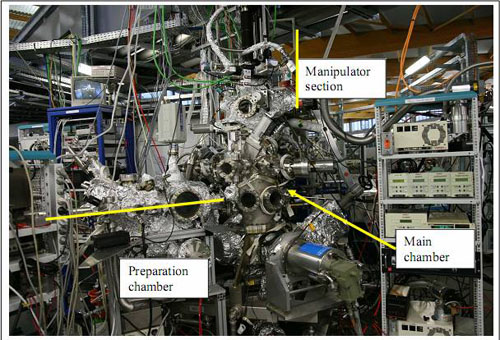
A mass spectrometer, a differential sputter gun and a parking for three sample holder are placed at the transfer level. The main chamber is pumped by a Turbo pump, an ion pump and a cry pump. All the pumps can be isolated from the main chamber with gate valves. Base pressure is 1x 10⁻¹⁰mbar.
Preparation Chamber
The preparation chamber is equipped with
- heating stage,
- sputter gun,
- leak valve for user treatments,
- mass spectrometer,
- fast entry lock stage,
- transfer rod,
- quartz microbalance
and three CF40 flanges placed in order to install evaporating sources on the axis of the sample at the heating stage level.
On the heating stage sample can be heated in two ways:
1) Current flow (for semiconductors) up to 10 A.
2) Electron bombardment of the sample holder using a filament to emit electrons and polarising the holder up to 1000 Volts.
The transfer rod is equipped with a carousel for four sample holders and is used to bring sample in the main experimental chamber.
The chamber is pumped by a turbo pump and a Liquid Nitrogen trap with a Ti sublimator.
TEMPO sample holders
Sample environment for sample annealing by current flow.
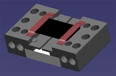
Porte-échantillon pour semi-conducteur.
Les matériaux sont en tantale et nitrure d’aluminium.
Température atteinte : jusqu’ à 2000°C
Espace pour échantillon : 5 x 10 mm
Sample environment for measuring magnetic properties
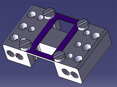
Porte-échantillon pour application d’un champ magnétique (1000 Oe)
Espace pour échantillon : au moins 5 x 10 mm
Matériaux : Molybdène munis de 4 écrous tantale M1.4
Température atteinte : jusqu’ à 2300K
Free station branch
Spot size on the branch line
The spot size has been measured positioning a fluorescent YAG screen at the sample position and taking an image with CCD camera and a calibrated magnification optic placed at about 300 mm. In the figure on the left we show the 3D representation of the photon beam intensity obtained from the image presented in the central figure. It was obtained with an exit slit aperture of 50μ. It is compared to the ray tracing calculation for the same field of view: 300μ x 300μ. The branch-line has been used for the gas phase experiments which characterized the beamline energy resolution and by three external user experimental stations:
- X-PEEM Laboratoire Louis Néel, Grenoble (Jan Vogel)
- NanoESCA , Laboratoire LETI, Grenoble (O. Renault)
- Coherent Scattering experimental station , Sextant Beamline, Soleil (Jan Luning, M. Sacchi)
Spot size image recorded on the TEMPO branch line on a fluorescent screen with a CCD camera.
Shipping goods
Fausto Sirotti
Ligne TEMPO
Synchrotron SOLEIL
Orme des Merisiers
BP 48 - Saint Aubin
91192 - GIF-SUR-YVETTE