Caractéristiques du faisceau
L'anneau de stockage a été conçu pour satisfaire toutes les catégories d'utilisateurs, tant par le choix de l'énergie nominale de fonctionnement de la machine que par les cinq modes de fonctionnement possibles.
Paramètres des accélérateurs
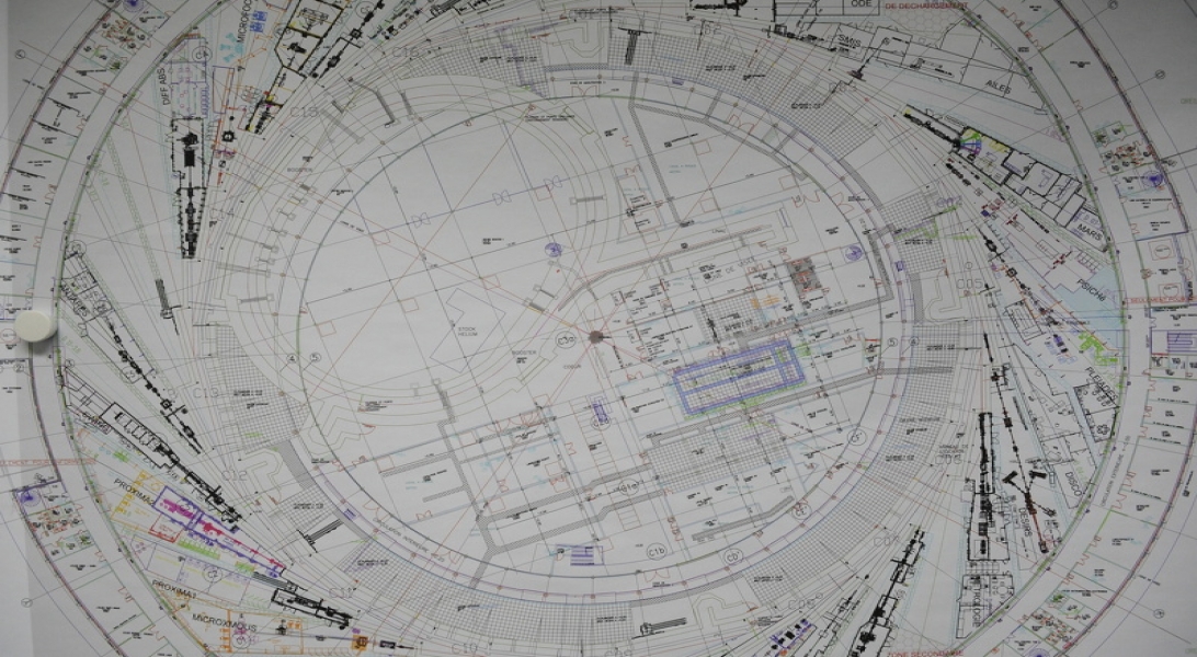
La machine SOLEIL est composée de 2 accélérateurs (un accélérateur linéaire le LINAC et un accélérateur circulaire le booster) et d'un anneau de stockage, polygone de 354 m de périmètre.