Recherche & Développement
La conception et la construction, ainsi que l'exploitation des lignes de lumière et des accélérateurs de SOLEIL, s'appuient sur des groupes techniques de support: Optique, Détecteurs, Ingéniérie mécanique, Électronique, Informatique, Alignement et Métrologie, Magnétisme, Alimentations, Ultravide, Diagnostics, Radiofréquence, ... Afin de mettre à la disposition des utilisateurs de SOLEIL des installations expérimentales parmi les plus performantes au monde, ces groupes support conduisent de nombreux projets de Recherche & Développement, parfois en collaboration avec d'autres laboratoires, ou des partenaires industriels.
Leur objectif : développer des équipements de pointe, construits sur mesure en fonction des besoins et des contraintes exprimés par les scientifiques.
Avancées technologiques
Depuis la conception, puis l'installation, jusqu'à la phase d'exploitation de SOLEIL aujourd'hui, les travaux de Recherche et Développement conduits par les goupes support et les lignes de lumière ont conduit à de nombreuses innovations technologiques.
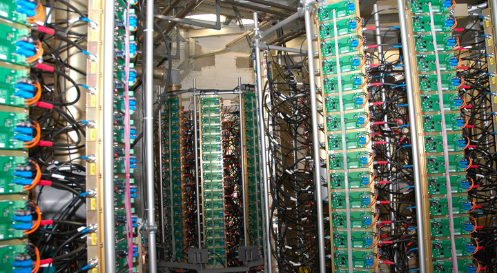
Que ce soient des améliorations des performances des accélérateurs, des dispositifs optiques de pointe sur les lignes de lumière, des détecteurs toujours plus performants, ... certaines de ces innovations ont fait l'objet de partenariats industriels et de transferts technologiques.
Supports aux utilisateurs
SOLEIL est présent aux côtés des utilisateurs pour les aider à préparer et réaliser leurs expériences, grâce aux équipements et à l’expertise des équipes de plusieurs laboratoires situés dans le bâtiment synchrotron, au plus près des lignes de lumière.
Le Groupe de Réduction et d'Analyse des Données (GRADES) apporte son soutien aux utilisateurs pour le traitement de l’ensemble de leurs données expérimentales.
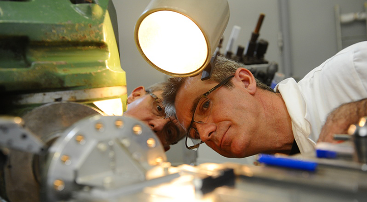
Laboratoire de Métrologie Optique
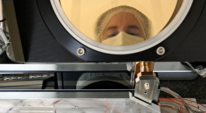
Accrédité par le COFRAC en 2022, Le Laboratoire de Métrologie Optique (LMO) a la charge de la caractérisation des optiques (miroirs et réseaux) montées sur les Lignes de lumière du Synchrotron SOLEIL.
Pour cela il dispose d’un parc d’instruments dédié à la cartographie des surfaces : profilomètre optique, interféromètres, microscope à force atomique et analyseurs de front d’ondes.
Les services du LMO sont également disponibles aux industriels par l’intermédiaire du Groupe des Relations Industrielles et de la Valorisation de SOLEIL.
Jouvence de la station de production d'eau glacée

Le Synchrotron SOLEIL bénéficie d'un financement dans le cadre du plan France Relance pour moderniser la station de production d'eau glacée de son site.