TEMPO est une ligne de lumière X-mous optimisée pour les études dynamiques des propriétés électroniques et magnétiques des matériaux, en utilisant la spectroscopie de photoélectrons.
 Opérationnelle depuis fin 2007, la ligne de lumière TEMPO permet d’effectuer des études en photoémission et en photoabsorption dans la gamme des rayons x-mous. La spécificité de l’installation réside dans la prise en compte de la variable temporelle. La ligne traite particulièrement des sujets suivants :
- Détermination des cinétiques de réaction en surface et à l’interface par photoémission rapide à l’échelle de la milliseconde. Grace à l’important flux de photons et à la bonne résolution en énergie, l’évolution de l’environnement chimique (coordination de surface, liaison avec des éléments chimiques différents) des atomes sélectionnés à la surface peut être étudié en fonction du temps en utilisant des signatures spectroscopiques dans les états électroniques. Les applications possibles sont les cinétiques de physisorption, chimisorption ou dissociation de molécules sur un substrat, formation d’interfaces et interdiffusions. La compréhension de ces phénomènes sont essentiels pour la préparation de nouveau matériaux magnétiques et pour contrôler la réactivité chimique et les propriétés catalytiques.
- La mesure de la dynamique de l’aimantation dans les nanostructures, en utilisant les caractéristiques temporelles (à l’échelle des dizaines de picosecondes) de Soleil, est un des enjeux les plus importants dans le domaine du stockage de l’information à haute densité. Les expériences peuvent se faire en utilisant des techniques avec une profondeur de mesure variable : dichroïsme circulaire magnétique, dichroïsme magnétique en photoémission.
- Réalisation d’expériences pompe sonde avec deux photons (laser + rayonnement synchrotron, dans la gamme temporelle des picosecondes) pour des études d’états excités.
La ligne de lumière TEMPO est le résultat du transfert de la ligne SB7 [1] de SuperACO sur des éléments d’insertion de Soleil. Elle couvre la gamme d’énergie entre 50 eV et 1500 eV. Cette gamme en énergie est particulièrement bien adaptée aux études des matériaux magnétiques et aux applications dans le domaine de la chimie. À faible énergie de photons on peut effectuer de la spectroscopie UPS sur la bande de valence. A Plus haute énergie de photons nous avons à disposition les seuils K des molécules organiques (C,N,O, F), les seuils L des métaux de transitions (avec des applications possibles aux molécules métallo-organiques et aux surfaces des métaux), les seuils M des terres rares.

L'équipe
Données techniques
50 – 1500 eV
E/ΔE mieux que 104
Eléments d'insertion HU80 et HU44 de type Apple II
2.1015 Phot/s/0.1% bw à 100eV
Focalisation par miroirs toriques pour séparation femtoseconde dit "slicing".
Monochromateur : Réseaux plans VGD et miroirs sphériques.
2 stations expérimentales fonctionnent alternativement.
Environ 4 1013 Phot/s/0.1% bw
Polarisation variable (Circulaire, linéaire horizontale et verticale)
10x40 μm2 (1ere branche); 100x100 μm2 (2e branche)
Environnement échantillon
Préparation
Chambre de préparation, système de transfert d'échantillon avec sas d'introduction ; bombardement Argon ; évaporateurs refroidis à l'eau ; Porte-échantillons pour métaux ; échantillons semiconducteurs conventionnels et cristaux multicouches (graphite,MoS etc.)
Caractérisation
LEED, Effet Magneto optique Kerr, échantillon refroidi à 50 K et chauffé à 1200 K.
Detecteur
Analyseur d'électron SCIENTA 2002 avec détecteur 2D à ligne à retard pour des expériences résolues en temps.
Station prête pour le montage expérimental de photoémission à pression proche de l'ambiante NAP-XPS propriété de l' UPMC (Paris)
Thématiques scientifiques
|
Science des surfaces |
|
|---|---|
| Magnétisme |
|
| Chimie |
|
| Recherche appliquée |
|
En recherche interne à SOLEIL, la ligne de lumière TEMPO est rattachée à la section scientifique :
| Section scientifique SOLEIL | Surfaces, Interfaces and Nanosystems. |
|---|

TEMPO est une ligne de lumière dans la gamme des x mous, conçue pour les études résolues en temps des propriétés électroniques et magnétiques des matériaux en utilisant la spectroscopie de photoélectrons.
Source
La ligne de lumière est équipée de 2 onduleurs hélicoïdaux APPLE II. Ils ont une période de 44 mm et 80 mm ce qui permet de couvrir toute la gamme d’énergie de la ligne avec le premier harmonique.

La photo montre les 2 insertions installées dans la section droite n° 8 de Soleil. Le faisceau se propage de la gauche vers la droite de l’image. L’onduleur HU80 est quasi périodique pour déduire autant que possible les harmoniques élevées du faisceau de photons.

arrangement magnétique ligne TEMPO
Calibration et alignement des insertions
La calibration en énergie de l’émission des dispositifs d’insertion est un point critique du fonctionnement de la ligne de lumière en termes de flux, polarisation et de la fiabilité de l’installation.
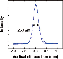
Depuis le tout début de la mise en service de la ligne cette activité a été faite en collaboration avec le groupe « magnétisme et insertions » de Soleil (GI). Des tables de calibration pour les valeurs de gaps et de phases des insertions ont été calculées par GI en fonction de l’énergie des photons pour accorder nos résultats obtenus en mesurant le spectre d’émission de l’onduleur. La calibration a été faite pour 4 polarisations : linéaire vertical et horizontal, circulaire droite et gauche. Un point essentiel dans la procédure de calibration était de définir parfaitement le cône d’émission de l’onduleur et la position de son centre. Le diaphragme a été fermé à 400 µm et scanné dans le plan horizontal et vertical. Pour chaque position nous avons obtenu les spectres en énergie présentés Fig. 1. En bougeant l’axe de l’onduleur, l’intensité croit et le maximum de flux est centré sur les hautes énergies de photons. Dans l’encart sont représentés les intensités maxima et les énergies de photons au maximum d’intensité à partir des spectres, en fonction de la position du diaphragme.
Fig. 1: Spectre du flux de photons mesuré en fonction de l’énergie de photons obtenu en scannant verticalement le diaphragme fermé à 400 µm. Les mesures ont été réalisées à partir d’une photodiode calibrée, placée à la position échantillon. L’intensité maximum et l’énergie correspondant au maximum de flux sont présentées dans l’encart en fonction de la position du diaphragme pour définir l’axe de l’onduleur.
Fig. 1: Spectre du flux de photons mesuré en fonction de l’énergie de photons obtenu en scannant verticalement le diaphragme fermé à 400 µm. Les mesures ont été réalisées à partir d’une photodiode calibrée, placée à la position échantillon. L’intensité maximum et l’énergie correspondant au maximum de flux sont présentées dans l’encart en fonction de la position du diaphragme pour définir l’axe de l’onduleur.
SR Extraction
La première chambre miroir est placée dans la cabane radioprotection à environ 20 mètre de la source. Le faisceau de photons est d’abord dévié par un miroir plan. Suivant l’angle d’incidence il peut suivre 2 chemins optiques caractérisés par une déflexion angulaire de 2 et 4 degrés. Le faisceau est ensuite réfléchi par un miroir torique placé à 2 ou 4 degrés pour respectivement une haute et basse énergie de photons.
Les miroirs en silicium sont recouverts de platine et refroidis à 100K par un circuit fermé d’azote liquide à haute pression.

La photo montre dans la salle blanche les 3 supports durant l’alignement des miroirs. Les tubes de cuivre permettent le passage en circuit fermé de l’azotliquide.
Diagnostiques d'alignement
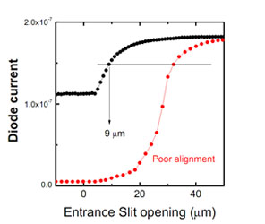
Deux fentes sont placées au point focal horizontal et vertical des miroirs. L’intensité transmise est utilisée comme diagnostique pour l’alignement des miroirs d’extraction. Sur la gauche on peut voir le profil de l’intensité du faisceau obtenu en scannant horizontalement une fente verticale de 50 microns d’ouverture, placée avant les réseaux. Cela nous permet de déterminer la qualité de l’alignement dans le plan horizontal. L’intensité transmise présentée à droite est mesurée en scannant l’ouverture de la fente d’entrée. La dimension du faisceau dépend de l’énergie des photons, mais lorsque l’alignement est bon, plus de 50% de l’intensité est transmise à travers l’ouverture minimale de la fente qui est de 5 microns.
Le monochromateur
Le monochromateur se compose de 3 réseaux plans et de 2 miroirs sphériques. Les réseaux présentent un espacement variable entre traits (VLS) pour focaliser le faisceau sur la fente de sortie et une profondeur de gravure variable (VGD) pour optimiser le flux total de photons et la réjection d’harmonique pour chaque énergie de photons..

monochromateur composé de 3 réseaux plans et de 2 miroirs sphériques
Le monochromateur est donc caractérisé par 2 chemins optiques : l’un pour les basses énergies, l’autre pour les hautes énergies. Les intervalles d’énergie de photon sont résumés ici :
| Chemin optique basse énergie (miroir A) : | Chemin optique haute énergie (miroir B) : |
|---|---|
|
|
Procedure d'alignement

Photo prise pendant le premier alignement du monochromateur. L’alignement a été soigneusement vérifié par les groupes Métrologie et Optique.
Résolution énergétique
Les tests de résolution ont été réalisés en mesurant le spectre de rendement ionique aussi bien dans la gamme d’énergie près de l’excitation résonnante 2p de l’argon atomique, que de la série de Rydberg de l’hélium ou de l’excitation 1s de la molécule d’azote. Le spectre a été obtenu en suivant le nombre total d’ions produit dans la région d’interaction entre le rayonnement synchrotron monochromatique et un jet de gaz émanant d’une buse très fine. Les résultats obtenus pour l’hélium, l’argon et l’azote sont montrés dans graphiques suivants.
Le pouvoir résolvant E/ΔE est mieux que 10 000 pour les trois énergies.
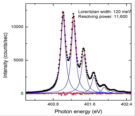
Nitrogen 1s absorption edge
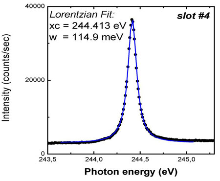
Ar absorption
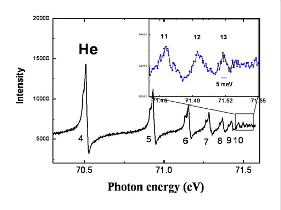
He
Refocussing
Dimension du faisceau sur la 2e branche
La dimension du faisceau a été mesurée en positionnant un écran YAG fluorescent à la position échantillon et en prenant une image à l'aide d'une caméra CCD et une optique de grandissement calibrée placée à environ 300mm (S. Kubsky, Laboratoire de Surface).

Representation 3D de l'intensité du faisceau de photons
Representation 3D de l'intensité du faisceau de photons
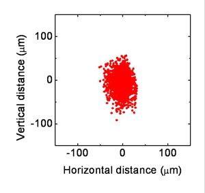
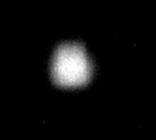
Comparaison d'une image obtenue par calcul (à gauche) et celle enregistrée par la caméra pour un champ visuel de : 300μm x 300μm.
Station exp #1: UHV Photoémission
Photoémission UHV
La branche principale de la ligne TEMPO est équipée d’une station dédiée aux expériences de physique des surfaces. Elle se compose d’une chambre principale munie d’un analyseur d’électrons Scienta SES 2002 lui-même équipé d’un détecteur à ligne à retard, et d’une chambre de préparation avec un système de transfert d’échantillons et d’un sas d’introduction rapide. On y dispose d’un bombardement d’Argon, des évaporateurs refroidis à l’eau et une caractérisation par LEED. Nous avons développé 2 environnements échantillon : l’un pour des expériences de dichroïsme magnétique ou un champ de 100 Oersted peut être appliqué en position de mesure, l’autre pour le chauffage direct d’échantillons semi-conducteurs par passage de courant.

La chambre expérimentale de photoémission en 2008
La chambre expérimentale de photoémission en 2008
Détecteur pour des expériences résolues en temps
Une partie importante du projet scientifique de la ligne TEMPO est basée sur des expériences de photoémission résolues en temps utilisant la technique pompe-sonde. Des applications possibles sont l’étude de la structure électronique des états excités par laser ou les dynamiques de magnétisation de surface.
La durée de relaxation de ces phénomènes peut être plus longue que la période entre paquets. Il est alors indispensable d’associer chaque photoélectron détecté au paquet synchrotron qui l’a créé. Si cette identification est possible, la cadence de répétition de la pompe peut être utilisée pour les expériences et l’état excité par le laser peut être sondé par le pulse synchrotron en fonction du délai entre deux pulses.
La résolution en temps de l’expérience est alors seulement limitée par la longueur du paquet synchrotron : 30 ps à Soleil.
Nous avons modifié l’analyseur Scienta en remplaçant la caméra CCD par un détecteur à ligne à retard (équipe de G. Cautero, Elettra, Trieste, Italie) qui peut associer chaque photoélectron à la cadence du synchrotron. Cette nouvelle configuration nous permet de réaliser des expériences de spectroscopie de photoélectron en utilisant le paquet isolé lorsque Soleil est injecté en mode hybride.

Dans cette figure l’intensité de photoémission mesurée en fonction de la durée totale de révolution (environ 1.2 µs) est comparé à la structure des paquets synchrotron pendant un run en mode hybride.
Station exp #2
Ce point focal a été utilisé pour le commissioning du faisceau de photon. Nous y avons réalisé des expériences en phase gaz (M. Meyer, LIXAM) pour mesurer le pouvoir résolvant du monochromateur et le flux total à l’aide d’une photodiode calibrée.
Première image du faisceau de photons au point focal relevée sur la ligne TEMPO
La photo a été prise le 12 février 2007 avec le monochromateur en mode réflexion totale. Le bon centrage du faisceau est le résultat du bon travail effectué par le groupe alignement.
Des expériences avec des utilisateurs extérieurs ont été installées à ce point focal :
XPEEM du Lab. L. Néel (Grenoble)
Le PEEM venant du laboratoire Louis Néel (Jan Vogel) a été installé à plusieurs reprises sur cette branche depuis 2008 pour réaliser des expériences de dynamique d’aimantation.

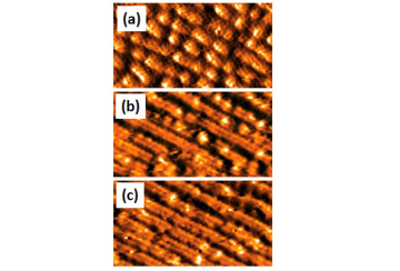
(a) Structure en domaines magnétiques de nano fils après application d’impulsions de champ magnétique.
(b) Structure en domaines après application d’une impulsion de courant de 10 ns de durée, avec une densité de courant de 4.2 x 10¹¹ A/m2. La direction du flux d’électrons est indiquée sur la photo. Les flèches blanches indiquent des parois de domaine qui se sont déplacées dans la direction du flux d’électrons. Les flèches bleues pointent vers un nouveau domaine qui était nucléé.
(c) Structure en domaine après application d’une impulsion identique mais en sens contraire. Certaines parois de domaine, indiquées par les flèches blanches, sont revenues en arrière dans la direction opposée. Ces résultats confirment que le mouvement de paroi de domaine est dû à l’effet du couple de spin induit par le courant polarisé de spin. Cependant, le mouvement de paroi de domaine n’est pas parfaitement réversible
(a) Structure en domaines magnétiques de nano fils après application d’impulsions de champ magnétique.
(b) Structure en domaines après application d’une impulsion de courant de 10 ns de durée, avec une densité de courant de 4.2 x 10¹¹ A/m2. La direction du flux d’électrons est indiquée sur la photo. Les flèches blanches indiquent des parois de domaine qui se sont déplacées dans la direction du flux d’électrons. Les flèches bleues pointent vers un nouveau domaine qui était nucléé.
(c) Structure en domaine après application d’une impulsion identique mais en sens contraire. Certaines parois de domaine, indiquées par les flèches blanches, sont revenues en arrière dans la direction opposée. Ces résultats confirment que le mouvement de paroi de domaine est dû à l’effet du couple de spin induit par le courant polarisé de spin. Cependant, le mouvement de paroi de domaine n’est pas parfaitement réversible.
NanoEsca CEA sur TEMPO
Le spectromicroscope NanoESCA (Omicron Nanotechnology) du CEA, permettant la réalisation d’expériences d’XPEEM spectroscopique (c-à-d, résolues en énergie), a été installé en juillet 2009.
Le filtrage en énergie des images XPEEM se fait grâce à un double analyseur hémisphérique qui, en compensant les aberrations inhérentes à un filtrage classique réalisé à partir d’un seul analyseur, confère au système la haute transmission nécessaire (gain d’un facteur 650) à l’enregistrement d’images à haute résolution énergétique (jusqu’à 100 meV) formées avec les photoélectrons des niveaux de cœur ou de valence. Cette haute transmission fournit en outre la statistique de comptage nécessaire pour conserver une bonne résolution latérale (Δx=100 nm et moins en imagerie des niveaux de cœur).
Avec cet instrument installé de façon temporaire nous avons effectué les toutes premières expériences d’XPEEM filtré en énergie avec la source SOLEIL.

The NanoEsca experimental Station @ TEMPO
The NanoEsca experimental Station @ TEMPO
La ligne TEMPO est ouverte aux utilisateurs exterieurs depuis décembre 2007. Sur cette page vous trouverez une brève description des projets de recherche et la liste des utilisateurs extérieurs
Collaborations
Laboratoire de Chimie Physique - Matière et Rayonnement
Université Paris VI
11, rue Pierre et Marie Curie
75 231 Paris Cedex 05
Francois Rochet
Jean Jacques Gallet
Fabrice Bournel
George Dufour
Construction et commissioning de la station expérimentale principale (photoémission UHV) et de la chambre de préparation.
web site: http://www.lcpmr.upmc.fr/theme2.html
IDMAG, Laboratoire de Physique des Solides
Orsay, France
Gregory Malinowski
André Thiaville
Alexandra Mougin
web site : http://www.lps.u-psud.fr/collectif/gr_25/default.htm
APE Beamline
Elettra Synchrotron Light Laboratory
S.S. 14 Km 163.5, in Area Science Park
34012 Trieste (Italy)
Damjan Krizmancic
Développement logiciel pour le nouveau détecteur à lignes à retard installé sur l'analyseur d'électron et des programmes d'acquisition de la ligne.
Web site: http://www.elettra.trieste.it/experiments/beamlines/ape/index.html
Instrumentation and Detectors Labs
Elettra Synchrotron Light Laboratory
S.S. 14 Km 163.5, in Area Science Park
34012 Trieste (Italy)
Giuseppe Cautero
Luigi Stebel
Paolo Pittana
Rudi Sergo
Enrico Braidotti
Construction, installation et commissioning du nouveau détecteur à lignes à retard installé sur l'analyseur d'électron SES 2002 .
Web site: http://www.elettra.trieste.it/organisation/experiments/laboratories/instrumentation/
Liste des utilisateurs
Depuis l'ouverture officielle de la ligne de lumière en octobre 2007 nous avons réalisé plus de 60 projets utilisateur approuvés par les comités de programme Soleil. Quelques utilisateurs ont réalisé plusieurs projets et certains groupes ont participé ensemble au même projet. Ci-dessous la liste des groupes d'utilisateurs:
Paris Region
Laboratoire de Chimie Physique - Matière et Rayonnement,
Université Pierre et Marie Curie Paris VI
1. F. Rochet, J.J.Gallet, F. Bournel, G. Dufour
2. Boris VODUNGBO, Renaud DELAUNAY , Jan LUNING
3. Philippe PARENT, Carine Laffon
4. Pascal LABLANQUIE Francis PENENT, Lidija ANDRIC, Jérôme PALAUDOUX
5. Vita ILAKOVAC
Institut des NanoSciences de Paris
Université Pierre et Marie Curie Paris VI
6. M. Marangolo, Mahmoud EDDRIEF, Vincent Garcia, Franck VIDAL, Victor H. Etgens
7. Marie D D'ANGELO, Ian VICKRIDGE, Prof. Dr. Catherine N DEVILLE CAVELLIN
8. Nadine WITKOWSKI, Sophie BOUDET, Ieva BIDERMANE, Olivier Pluchery, Yves BORENSZTEIN
Laboratoire de Physique des Solides, Orsay
9. Andre Thiaville, Alexandra Mougin, Gregory Malinowski
Laboratoire des Solides Irradiés, Ecole Polytechnique
10. Mateo Guzzo, Giovanna Lani, Francesco Sottile, Lucia Reining
Synchrotron SOLEIL
11. Sextant Beamline : Maurizio Sacchi, Nicolas Jauen, Cédric BAUMIER, Horia POPESCU
12. HERMES Beamline : Rachid Belkhou
13. IPANEMA : Loic Bertrand, M. Languille
CEA Saclay
14. Claire MATHIEU, Julien RAULT, Bruno DELOMEZ, Nicholas BARRETT
15. Fabrice CHARRA
16. Fabien SILLY
17. Camille C.M. MARIE, Denis FICHOU
18. P.Soukiassian, Dr. Edward H CONRAD, Hanna B. ENRIQUEZ, Sebastien VIZZINI, Hamid OUGHADDOU
19. Laboratoire de Photonique et de Nanostructures, Marcoussis (Abdelkarim Ouerghi)
20. Institut de Minéralogie et de Physique des Milieux Condensés, Paris 6 (Dr. Abhay SHUKLA)
21. Centre de Spectrométrie Nucléaire et de Spectrométrie de Masse, Orsay (Franck FORTUNA)
22. Thales, Unité Mixte de Physique, Palaiseau (Abdelmadjid ANANE ,Vincent CROS)
France
23. Institut Néel, Grenoble (Stefania PIZZINI, Nicolas ROUGEMAILLE, Olivier FRUCHART, Jan VOGEL)
24. Spintonique et Technologie des Composants, Grenoble (Gilles GAUDIN)
25. Laboratoire de Chimie, Lyon (Gilles LEMERCIER, François LUX)
26. Institut de Physique et Chimie des Matériaux de Strasbourg (Christine BOEGLIN, Valérie HALTÉ, Eric BEAUREPAIRE, Jean-yves BIGOT)
27. Snecma Propulsion Solide (Sylvie LOISON)
28. Institut des Nanotechnologies de Lyon, Ecully (Bertrand R VILQUIN)
29. Fédération Micro- et Nano- Technologies MINATEC, Grenoble Cedex 09
(O. Renault, E. MARTINEZ, Clement GAUMER)
30. Institut Jean Lamour (Matériaux - Métallurgie - Nanosciences - Plasmas - Surfaces) Vandoeuvre Les Nancy (Antonio TEJEDA)
31. Laboratoire des Composites Thermostructuraux, Pessac (G. CHOLLON, C. PALLIER, P. WEISBECKER)
Europe
32. ELETTRA - Sincrotrone Trieste, Italy (Rudi SERGO, Enrico BRAIDOTTI, Paolo PITTANA, Giuseppe CAUTERO)
33. ELETTRA, Sincrotrone Trieste, Italy (Francesco D'AMICO)
34. Universita di Roma 'Roma Tre , Roma (Dr. Giovanni POLZONETTI, Dr. Chiara BATTOCCHIO, Dr. Giovanna IUCCI)
35. Universita of Camerino, Camerino, Italy (GUNNELLA Roberto, Mamatimin ABBAS)
36. Politecnico di Milano (Giovanni VANACORE, Maurizio ZANI, Giovanni ISELLA, Alberto TAGLIAFERRI)
37. University of Pisa , Italy(Michele VIRGILIO, Giuseppe GROSSO)
38. University of Milano Bicocca, Italy (Monica BOLLANI)
39. Forschungszentrum Jülich (Ingo P. KRUG, . Dr. Claus M. SCHNEIDER, Adrian PETRARU)
40. Max Plank Institut for Polymer Research, Mainz (Prof. Dr. Klaus MUELLEN)
41. School of Physics and Astronomy - Univ. of Manchester (Prof. Dr. Wendy R FLAVELL, r. Samantha J HARDMAN, Darren M GRAHAM, Ben F SPENCER
42. Reading University, Reading, UK (Georg HELD, Andrey SHAVORSKIY)
43. Uppsala University, Sweden(Carla PUGLIA, Emmanuelle GOTHELID)
44. Linköping University, SE (Yiqiang ZHAN, Prof. Dr. Mats FAHLMAN)
45. Royal Inst. for Cultural Heritage, Bruxelles, (Amandine C. CRABBÉ , Helena J. M. WOUTERS)
46. Vrije Université Brussel, Bruxelles , (Isabelle VANDENDAEL, Prof. Dr. Herman TERRYN)
47. IMEC, Leuven (Clement MERCKLING, Julien PENAUD)
48. Research Institut for Technical Physics and Materials Science, Budapest (Gabor BATTISTIG, Anita PONGRACZ)
49. Centre d'Investigaciò en Nanociència i Nanotecnologia, Bellaterra (Barcelona) (Ioan mihai MIRON, Pietro GAMMBARDELLA)
50. Univ Autonoma de Madrid, Spain (Erika JIMENEZ, Julio CAMARERO)
51. Jozef Stefan Inst, Ljubljana (Klemen BUCAR)
52. University of Oulu, Finland (Marko HUTTULA)
53. IBM Research GmbH, Rueschlikon, Suisse (Lukas CZORNOMAZ, Dr Mario EL KAZZI, Chiara MARCHIORI)
54. Universita di Roma, Tor Vergata, Italy (Paola CASTRUCCI, Maurizio DE CRESCENZI, M. SCARSELLI, S. DEL GOBBO, L. CAMILLI)
Autres pays
55. Institut National de la Recherche Scientifique, Varennes, Canada (J. LIPTON-DUFFIN, J. MACLEOD, F. ROSEI)
56. School of Physics - Georgia Institut of Technology, Atlanta(Jeremy HICKS)
57. Centro de Desenvolvimento da Tecnologia Nuclear CDTN, Belo Horizonte Brasil (Dr. Waldemar A. A. MACEDO, Maximiliano MARTINS)
58. Institut for Soleil State Physics, University of Tokyo, Japan , (Iwao MATSUDA, Manami OGAWA)
59. Photon Factory, Tsukuba, Japan (Kenji ITO)
60. UVSOR facility, Okazaki, Japan (Yasumasa HIKOSAKA, Eiji SHIGEMASA)
61. Niigata University Niigata, Japan (Kouichi SOEJIMA)
62. University of Oulu, Oulu , Japan(Marko HUTTULA)
Statistiques utilisateurs
Plus de 20 projets approuvés par les comités de programme réalisés chaque année.
Les projets sont distribués sur les 2 branches expérimentales :
- UHV photoémission
- Station disponible pour tout équipement utilisateur externe
Sunset
Configuration de la station expérimentale
La station expérimentale sur la ligne principale est dédiée aux expériences de spectroscopie de photoémission. Elle est composée d’une chambre principale UHV, une chambre de préparation et d’une partie manipulateur. La chambre principale est équipée d’un analyseur d’électrons Scienta SES 2002 ainsi que d’un système LEED (Specs) placés au niveau du faisceau de photons. Un manipulateur Omniax de 600 mm de course est disposé verticalement et il peut déplacer l’échantillon du plus haut niveau (partie manipulateur seul) au niveau le plus bas pour le transfert d’échantillons.
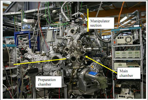
Un spectromètre de masse, un canon à électrons, un canon pour le bombardement ionique et un parking motorisé pour 3 échantillons équipent la chambre d’analyse, niveau transfert. Son pompage est turbo moléculaire, ionique, cryogénique est comporte un getter (SAES). Toutes les pompes peuvent être isolées de la chambre par des vannes manuelles. La pression de base est de 1x10⁻¹⁰ mbar.
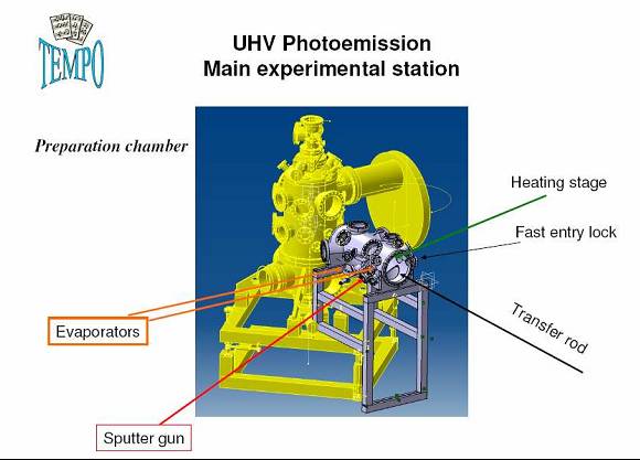
Chambre de préparation
La chambre de préparation est équipée de :
- SAS d'introduction rapide des échantillons
- four pour recuit par passage de courant direct sur support échantillon semi-conducteur
- four pour recuit par bombardement électronique des supports échantillon magnétisme
- Canon pour le bombardement ionique (Ar+)
- Vannes de fuite pour les traitements échantillon sous atmosphère contrôlé (10-5mBar)
- balance à quartz
- 3 emplacements CF40 pour des évaporateurs visant l’échantillon sur le four en position de chauffage
- Canne de transfert vers chambre d’analyse
Le chauffage échantillon peut être effectué soit par passage de courant jusqu’à 10 A (semi-conducteurs), soit par bombardement électronique du porte-échantillon avec un filament d’émission d’électrons et d’une tension de polarisation jusqu’à 1000V.
La canne de transfert est équipée d’un carrousel pour 4 porte-échantillon et permet leur déplacement dans la chambre d’analyse.
 La chambre est pompée par une pompe turbo moléculaire et un sublimateur de titane.
Porte-échantillons
Environnement échantillon pour recuit par passage de courant
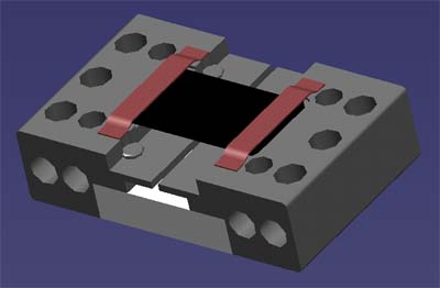
Porte-échantillon pour semi-conducteur.
Les matériaux sont en tantale et nitrure d’aluminium.
Température atteinte : jusqu’ à 2000°C
Espace pour échantillon : 5 x 10 mm
Environnement échantillon pour mesure de propriétés magnétiques
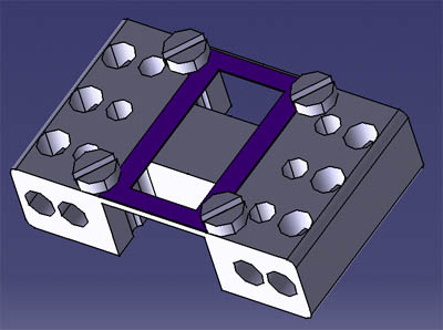
Porte-échantillon pour application d’un champ magnétique (1000 Oe)
Espace pour échantillon : au moins 5 x 10 mm
Matériaux : Molybdène munis de 4 écrous tantale M1.4
Température atteinte : jusqu’ à 2300K
Deuxième branche
Dimensions du faisceau sur la 2e branche
Le faisceau focalisé a été mesuré en positionnant un YAG fluorescent à la position échantillon en traitant une image donnée par une caméra CCD et utilisant une optique calibrée de grandissement placée à environ 300 mm. La figure ci-dessous montre une représentation 3D de l’intensité du faisceau de photon obtenu avec une fente de sortie de 50µ. La mesure donne une dimension de 100µ x 100µ. Cette branche a été utilisée dans les expériences en phase gaz pour caractériser la résolution en énergie de la ligne et par 3 dispositifs expérimentaux :
- X-PEEM Laboratoire Louis Néel, Grenoble (Jan Vogel)
- NanoESCA Laboratoire LETI, Grenoble (O. Renault)
- Dispositif expérimental de diffusion cohérente, Ligne de lumière Sextant, Soleil (Jan Luning, M. Sacchi)
Representation 3D de l'intensité du faisceau de photons
Image de la dimension du spot enregistrée sur la deuxième branche de Tempo sur écran YAG, avec caméra CCD